top of page
Microwave Heater
Introduction:
The senior design project assigned in MMAE 432 was to come up with a microwave that will heat up more area on food but to also measure the temperature of the food that is being cooked or heated. The microwave needed to heat up more than 85% of the total area of the food. The changes that we made to the microwave was to add an infrared temperature sensor at the top of the microwave which will then output the temperature on an LED screen.The main mechanism that lead to the overall heating of food to increase was a lead screw that was 3D printed which was powered by a DC motor. The lead screw turned, but what moved up and down was a screw nut which was attached to the microwave plate. All this components were kept inside a box that was made out of acrylic and the reason why acrylic was chosen was because it was easier to machine or cut as it was sized using the laser cutter.
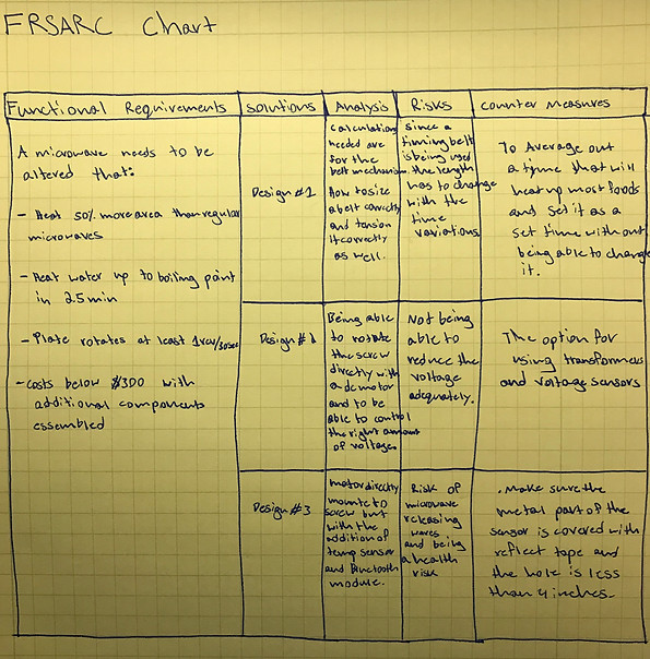
Functional Requirements
-
Heat 50% more area than regular microwaves.
-
Plate rotates at least 1 rev/30 sec.
-
Costs below $300 with all the additional components assembled.
Description:
A FRSAEC chart was created and is shown in table 1. It starts out with our functional requirements for the microwave. Then there were three concept designs with different ways to approach the problem. The first design was to have a timing belt/pulley system which will then rotate the lead screw and then raise the microwave plate using the original microwave motor which will only turn in one direction. The main risk with this design was that our timing belt had teeth on one portion of the belt while the other portion did not. To turn the lead screw up, a certain timing pulley will be driven and then to lower the lead screw the same pulley cannot be driven and the portion of the belt with no teeth will be in contact with the pulley. The second design is more simplified as the belt and pulley mechanism are replace by a direct programmable motor mounted onto the lead screw. The third design is just like the second design but an infrared temperature sensor is added, more like a feature. The sensor will read the temperature up to a depth of 10cm and a radius of 10cm.
Concept Generation
Prototyping & Analysis & Construction


Description:
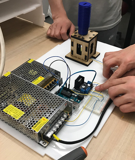
The mechanism that was made to power the motor as well as program it was two transformers, breadboard, Arduino, and a voltage sensor which can be seen at the top left. One of the transformers is to convert 120 volts to 12 volts coming from the wall socket to power the 12-volt DC motor. The second transformer is to convert the voltage coming from the microwave to the voltage sensor. Once the voltage sensor senses that the microwave is on, it will then send power to the motor to turn a certain amount of revolutions depending on the time the consumer will input.
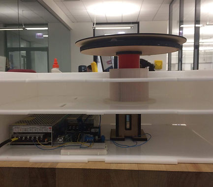
The other part of the design was the actual lead screw with the nut that will move up and down the microwave plate. Traditional metal lead screws could not be used on this type of application so these parts were 3D printed with a M36x4 thread. Also, a round guide was 3D printed with 3 side grooves for metal balls to be able to roll up and down. The metal balls were used for easier rotational movement to convert the motion to linear motion. The metal balls were greased to reduce friction which are commonly used in ball screws. The main key feature were the ball grooves, their main function was to keep the nut that was moving up and down the lead screw aligned and straight as seen on the top right.
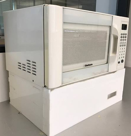
The first approach was to locate the spot where the sensor was going to be mounted. The sensor is made from stainless steel which cannot be inside the microwave. A 7cm hole was drilled on the second layer of the microwave so the sensor can sit on that plate but not go all the way through. No radiation should be zipping out as if the hole is smaller than 4 inches, then there will be no radiation coming out as the sensor base is glued to the metal cover. The sensor was programed using Arduino as well as the LED screen that was used to display the temperature. This was powered by three double AA batteries placed in series to achieve roughly 4.3 volts. The code used to program the Arduino and LED screen


Final Product
Description:
In this project, a good amount of mechanical and electrical knowledge was used as 60% of our design were electrical components. The prototype was built with the features that was intended to have such as the raising and lowering of the plate as well as the temperature reading. The material that was chosen to box these components was acrylic as it was the most convenient to cut due to laser cutting. For the functional requirements, it met all of them except the first one which was to be able to heat up 50% more area than the other microwaves. The estimate was about 42% more area out of the area that is not heated. The other requirement of one revolution per thirty seconds was relatively easy to achieve as it was just programing the DC motor.
The total cost to produce this final product is around $190. The most expensive material was the acrylic boards. From business stand point of view, this product will have to sell at around 30% margin which will come out to be $271 which is high on the consumer’s side.

bottom of page